Hack it!
LE STRUM is a pretty small device, on account of keeping the PCB costs down. However, the components and control surfaces are quite packed on to the PCB and it may be rather fiddly for serious performance use.
The good news is that LE STRUM is designed to be hackable - there are various ways in which you can add your own control surfaces or enhance the existing ones. I have received several questions about adding new control surfaces to LE STRUM. If you transform your LE STRUM I’d love to see the result and will feature it on this wiki!
Adding Strings
There are plated holes in the PCB above and below each strum pad. You can use these to add your own “strings” by soldering wire between the pairs of holes. They give a more tactile strum but can “catch” the stylus a bit, so its really down to individual preference.
If you do add strings, make sure that you use a reasonably heavy gauge wire (to stop it stretching or snapping) and draw it down very tight when you fit it (so it cannot bend and touch the pad next to it). I used 24swg tinned copper wire but something even a bit heavier might be good. You could even solder the wires to the pads along their length to keep them in place (I haven’t tried this and dont know how it would feel). When strumming the wire, small flakes of metal dust can accumulate between the pads over time, so keep them clear to stop shorting.
With a bit of ingenuity you could raise the strings above the PCB on some kind of “bridge” (notched to hold the strings in place). This might give LE STRUM more of the feel of a stringed instrument, like a little zither or miniature autoharp. Perhaps it would be better to use proper steel guitar strings as they will be less likely to snap with over-enthusiatic strumming than copper wire. Again I have not tried this myself, but be sure to let me know if you do it and I will feature your build here!
Alternative Strum Surface
Why stop there…. you could replace the control surface completely; pads, buttons and stylus, and fit the PCB inside some other body to make a more ergononomic performance instrument! To do this you need to know a bit about how the electronics work.
Basically it is pretty easy to replace the pads and stylus. LE STRUM’s electronics “scan” across the 16 pads, outputting a short 5 volt pulse, while reading the voltage back at the stylus input. When the stylus reads the pulse back we know it is touching the pad that we are currently “pulsing”.
Replacing the pads is simple. Just wire your 16 replacement strings/pads to the existing ones, using the plated solder holes at the top or bottom end of each pad. You should probably keep your wiring as short as you can, to reduce electrical noise and capacitance issues, but a few inches of extra wiring per pad is not going to be a problem IMHO. Same with the stylus. There is an extra solder hole on the PCB for an alternative stylus, next to the original one.
If you wanted to, you could use switches, or any type of switching arrangement in place of a stylus/pad, although this might lose you the “strum”.
Alternative Chord Buttons Surface
You might also want to replace the chord buttons (and the mode button) with something bigger… Arcade buttons etc. just remember you’ll need 37 of them including MODE!
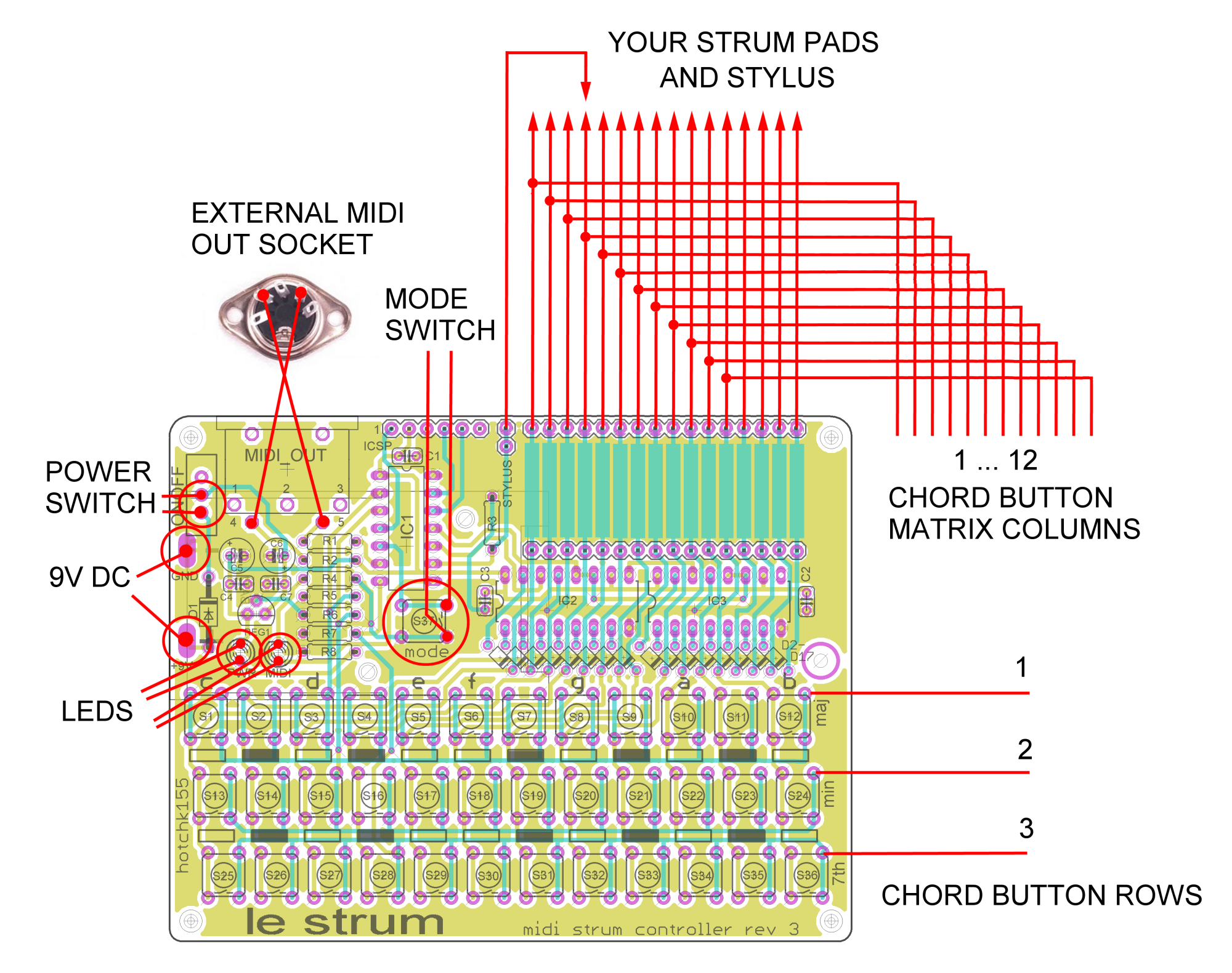
LE STRUM’s 36 chord buttons are “normally open” momentary switches arranged in 12 x 3 matrix. The 12 columns are wired to the same output lines as the first 12 strum pads, and follow the same sequence. This means you can easily use the plated PCB holes below/above the first 12 pads to wire up your switches.
To wire up a new switch matrix, arrange your 36 switches in 3 rows of 12. Wire one side of each column of three switches together, and connect to the appropriate strum pad.
Now wire the other side of the twelve switches in each row together. Each of the three resulting rows now needs to be connected to the three scan rows of LE STRUMs keyboard.
If you have the original switches fitted you can soldering to the existing solder connections to the right of the buttons in column “B” (i.e. the solder connections closest to the maj/min/7th labels on the PCB). It is not necessary to remove the original switches. They are “normally open”, so an external switch matrix should work fine with the switches in place.
If you did not solder the original switches you can simply solder to the appropriate holes of S12/S24/S36. Use the holes closest to the edge of the board. You can use either top or bottom hole, they are connected together.
Casing Up LE STRUM
If you are replacing the switches, you probably want to create a new body/case for your new instrument, so there are few more things we need to break out..
For the MODE switch you will need to connect directly to the existing switch connections or the PCB holes for S37 (if the switch is not fitted). Use the top-right and bottom-right holes.
If you want to bring out the LEDs, you will need to connect directly to the LED holes or solder connections.
To break out the MIDI connection only 2 wires are needed. These go to pins 4 and 5 of the MIDI connector on the PCB.
Connection Points
Here is my first strum controller, on stripboard. Granddaddy of LE STRUM. Notice the strings.
